|
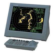
ARPA RADAR :FAR-28X7
古野雷达 : FAR-2817 / 2827 / 2837S 系列
23 inch High resolution Multi-color LCD
【雷达简介】
1) 功率: FAR-2817X : 12KW FAR-2827X : 25KW FAR-2837S : 30KW
2) 显示器:23.1' LCD
3) 有效显示直径:340mm
4) 天线: FAR-2817 / 2827 : 4 f t 6.5 f t 8f t FAR-2837S : 10 f t 12 f t
5) 量程:120nm
6) ARPA目标捕捉:自动50个,手动50个
7) AIS目标:可跟踪1000个AIS目标
8) 连接 AIS / GPS / LOG / ECDIS / COMPASS / VDR / SVDR
【Characteristics】
1: Advanced signal processing for improved detection in rough sea
2: LCD display providing crisp radar images
3: Designed to comply with SOLAS carriage requirements for ships 10,000 GT and above
4: Up to four radars can be interswitched in the network without an extra device
5: Automatic plotting/tracking of 100 targets manually or automatically acquired
6: Easy operation by customizable function keys, trackball/wheel palm module and rotary
controls Low spurious magnetrons meeting ITU-R unwanted emission standards
7: Displays 1000 AIS symbols
【Specifications】
|
General |
|
|
DISPLAY |
23.1" COLOR LCD |
|
ANTENNA |
FAR-2817X : 4, 6.5, 8 OPEN
FAR-2827X : 4, 6.5, 8 OPEN
FAR-2837S : 10 , 12 OPEN |
|
RANGE |
96 NM 、120NM |
|
POWER |
2817:12KW 2827:25KW 2837S:30KW |
【Antenna Radiators】 Type : Slotted waveguide array
|
Beamwidth and sidelobe attenuation : X-Band |
|
|
|
Radiator Type |
XN-12AF |
XN-20AF |
XN-24AF |
|
Length |
4 ft |
6.5 ft |
8 ft |
|
Beamwidth(H) |
1.9° |
1.23° |
0.95° |
|
Beamwidth(W) |
20° |
20° |
20° |
|
Sidelobe(within + 10°) |
-24 dB |
-28 dB |
-28 dB |
|
Sidelobe(outside + 10°) |
-30 dB |
-32 dB |
-32 dB |
|
|
|
|
|
|
Beamwidth and sidelobe attenuation : S-Band |
|
|
|
Radiator Type |
SN-30AF |
SN-36AF |
. |
|
Length |
10 ft |
12 ft |
. |
|
Beamwidth(H) |
2.3° |
1.8° |
. |
|
Beamwidth(W) |
25° |
25° |
. |
|
Sidelobe(within + 10°) |
-24 dB |
-24 dB |
. |
|
Sidelobe(outside + 10°) |
-30 dB |
-30 dB |
. |
|
|
|
|
|
|
Rotation |
|
|
|
X-Band: |
. |
. |
. |
|
|
Rotation |
24 rpm |
42 rpm |
|
|
Gear Box |
RSB-096/103 |
RSB-097 |
|
S-Band: |
. |
. |
|
|
. |
Rotation |
21/26 rpm |
45 rpm |
|
. |
Gear Box |
RSB-098/099 |
RSB-100/101/102 |
|
|
|
|
|
|
RF Transceiver |
|
|
Frequency |
X-band : 9410 MHz 30 MHz
S-band : 3050 MHz 30 MHz |
|
Output power |
FAR-2817 FAR-2827 FAR-2837S
Output Power 12kW 25kW 30kW
Transceiver RTR-078 RTR-079 RTR-080 |
|
Pulselength
/PRR |
Range scale (nm) Pulselength (s) PRR (Hz)
0.125, 0.25 0.07 3000
0.5 0.07, 0.15 3000
0.75, 1.5 0.07, 0.15, 0.3 3000, 1500
3 0.15, 0.3, 0.5, 0.7 3000, 1500, 1000
6 0.3, 0.5, 0.7, 1.2 1500, 1000, 600
12, 24 0.5, 0.7, 1.2 1000, 600
48, 96 1.2 600 |
|
I.F. |
60 MHz, Logarithmic |
|
Bandwidth |
Short pulse : 40 MHz
Middle pulse : 10 MHz
Long pulse : 3 MHz |
|
|
|
|
RADAR DISPLAY |
|
|
Display |
- 23.1" color LCD
- Effective display diameter : 340 mm
- Echo Color : Yellow, green or white in 32 levels |
|
Range scales and
ring intervals (nm) |
- Range:
.125, .25, .5, .75, 1.5, 3, 6, 12, 24, 48, 96
- Ring:
.025, .05, .1, .25, .25, .5, 1, 2, 4, 8, 16 |
|
Minimum range |
30* m on 0.75 nm range scale
*Using a 10 m2 test target at 3.5 m high above sea and antenna at 15 m high (IEC 62388).
Different conditions give a different result, maybe close to 20 m in actual installations. |
|
Range discrimination |
30 m |
|
Range ring accuracy |
1% of the maximum range of the scale in use or 30 m,
whichever is the greater |
|
Presentation modes |
Head-Up, Course-Up, North-Up, North-Up |
|
Heading information |
GPS compass SC-50/110 is a recommendable heading sensor as a backup for a gyrocompass.
Confirm if your Administrations permit its use. |
|
Parallel index lines |
1, 2, 3 or 6 lines (menu selectable) |
|
Radar map |
20,000 points to create coastlines, own ship safety contour, isolated underwater dangers, buoys, traffic routing systems, prohibited areas and fairways as required by IMO. |
|
|
|
|
Automatic Plotting |
|
|
Acquisition |
100 targets (e.g., manually 50, automatically 50) |
|
Tracking |
Automatic tracking of all acquired targets in 0.1 to 32 nm |
|
Guard zone
(Target Acquisition Area) |
Two guard zone, one of them 0.5 nm depth |
|
Vector |
True or relative, 30 s, 1, 3, 6, 12, 15, 30 min for prediction of target motion |
|
Past positions |
5 or 10 past positions at intervals of 30 s, 1, 2, 3, 6 min. |
|
Collision warning |
CPA limit : 0.2 - 10 nm,
TCPA limit : 0 - 99 min. |
|
Trial maneuver |
Dynamic or static, with selected delay time |
|
|
|
|
AIS FUNCTIONS (Data input from AIS is required) |
|
|
Symbols |
Sleeping, Activated, Dangerous, Selected, Lost targets |
|
Number of targets |
1,000 targets max. |
|
Data indication |
Basic and expanded data |
|
|
|
|
POWER SUPPLY (specify when ordering) |
|
|
Processor Unit |
24 VDC or 115/230 VAC, 50/60 Hz
440 VAC, 50/60 Hz with optional transformer RU-1803 |
|
Display Unit |
24 VDC or 100-230 VAC, 50/60 Hz
440 VAC, 50/60 Hz with optional transformer RU-1803 |
|
Antenna Unit |
FAR-2837S
230 VAC, 60 Hz; 38VAC, 50 Hz; 440 VAC, 60 Hz;
115 VAC, 60 Hz with optional transformer RU-5693
230 VAC, 50 Hz with optional transformer RU-6522
440 VAC, 50 Hz with optional transformer RU-5466-1 |
|
|
|
|
EQUIPMENT LIST |
|
|
Standard |
1. Display Unit : MU-231CR
2. Processor Unit : RPU-013
3. Full-keyboard Control Unit : RCU-014
4. Antenna Unit with cable : 15/20/30/50/100 m
5. Power Supply unit : PSU-007 for FAR-2837S
6. Standard Spare Parts and Installation Materials |
|
Option |
1. Performance Monitor :
PM-31 for FAR-2817/27
PM-51 for FAR-2837S (Specify when ordering)
2. Remote Control Unit : RCU-013
3. Gyro Interface :
GC-10 (built in Processor Unit)
4. DVI-Analog RGB Conversion Kit OP03-180 (SXGA output)
5. RGB Connector : DSUB-BNC-1 (for VDR)
6. Card Interface Unit : CU-200
7. Transformer : RU-1803/5466-1/5693/6522
8. Rectifier : RU-3424/1746B
9. Junction Box : RJB-001
10. Antenna Cable : RW-9600
11. Hand Grip : FP03-09840
12. Bracket : FP03-09820
13. Hub : HUB-100 |
|
|
|
ARPA RADAR :
23 inch High resolution Multi-color LCD
MODELS : FAR-2817 / 2827 / 2837S
FAR-21x7/28x7 Series Antenna Selection
Here is the list of antenna selection for FURUNO ARPA Radar FAR-21x7/28x7 series.
|
FAR-2117/2817 |
X-band, 12 kW, TR up |
|
FAR-2127/2827 |
X-band, 25 kW, TR up |
|
FAR-2827W |
X-band, 25 kW, TR down |
|
FAR-28137S/2837S |
S-band, 30 kW, TR up |
|
FAR-2837SW |
S-band, 30 kW, TR down |
100 Base-TX Ethernet Network System
The 100 Base-TX Ethernet is utilized to network up to four sets of FAR-21x7/28x7 series radar with ECDIS FEA-2107/2807. This Ethernet data link gives high-speed and stable navigational data sharing amongst the equipment networked within the system. This network capability gives options to choose from a single station system configuration to complete Integrated Navigation System (INS).
Target Tracking(TT: ARPA)/AIS
The FAR-21x7/28x7 series radar delivers full TT functionality and can plot up to 100 targets. In addition, this radar series is displaying up to 1,000 targets received from the AIS transponder system. Detailed information about the targets can be shown in data cells on right hand side of the screen. TT/AIS information scheme gives the operator full control over dense traffic. The type of AIS Symbol shows if it is a sleeping target, a normal target, a selected target, a dangerous target or a lost target.
AIS Symbols
COG/SOG vector changes its length with speed. ROT mark is viewable at the COG/SOG vector tip when a target has FURUNO Satellite Compass SC-50/110 or gyrocompass, which deal ROT serial sentence, installed.
TT Symbols
Target Association (Fusion)
Targets may be recognized both by AIS and TT and displayed with two respective symbols on the screen. This happens because the AIS position is measured by a GPS navigator in L/L, which the TT target are measured by range and bearing from own ship. Here, the TT symbols are merged into the AIS symbols, provided that both symbols are within operator-set criteria, which are determined by the differences in range, bearing, course, speed and others.
Stress-free Operation through Ergonomically-designed Control Unit
Stress-free operation with versatile control units
The control head has logically arranged operation scheme through a combination of push keys and a trackball. Well-organized menus ensure that all operations can be performed with a trackball.
Full-keyboard control head
Alternative to the Full-keyboard type or additional control head to be placed close to captain chair for remote operation. |